Notes
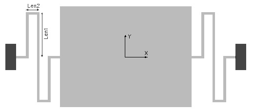
The serpentine beam is composed of two short beam segments folded
around in the shape of a 'S' and connected to either end of the
mass. The springs alternately compress and elongate as the mass
moves along the X axis. The figure shows two such beams attached to
the mass. Each of them could be formed of one or several such units
connected in series. This is designed to enable a translatory
motion of the suspension in the X axis or in an in-plane axis.
There is however a movement in the Z axis perpendicular to the
plane. The mass may have tendency to rotate about the X axis
also.
The linear stiffness of this beam in X and Z axes can be found out using this design interface. The torsional spring constant about the X axis can also be calculated as option 3. The length of the two segments can be optimized to increase or decrease the stiffness of the beam along the axis of interest.
The stiffness of a single serpentine beam is calculated. If the spring constant of one beam is k1 and the second spring is k2, and if they are connected in parallel, the effective spring constant
Kparallel = k1 + k2.
If the two springs are connected in series the effective spring constant is
1/Kseries = 1/k1 + 1/k2
The effective spring constant of the suspension can be calculated accordingly.
The plot shows how the spring constants in X, Y and Z axes vary with the length of the shorter section of a single serpentine beam while all other design parameters are as given in the design form. The X axis of the plot is Len2 as a percentage of Len1. Using the cross hair the value for stiffness in any of the 3 axes can be found out. It can be used to design the beam such that the stiffness for a particular axis is lesser or greater than the other axis. This will ensure that the suspended mass will have a higher tendency to move in the required axis.
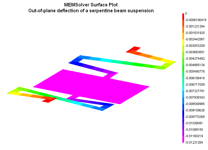
The 2D and 3D surface plots show the out-of plane deflection of the serpentine beam suspension.