Notes
Pressure driven, steady state flow of an incompressible fluid
through a straight microchannel is typically laminar in nature,
where the viscous effects dominate and inertial effects can be
neglected as characterized by very small Reynolds's number. Viscous
effects leads to internal friction in the fluid and creates
resistance to the flow of the fluid. Just like electrical
resistance leads to Joule heating, hydraulic resistance leads to
dissipation of kinetic energy into heat.
Understanding hydraulic resistance is vital to the design of a microchannel. Mathematically it is represented by the Hagen-Poiseuille law that relates constant pressure drop dP resulting in a constant fluid flow Q
dP = Rhyd Q
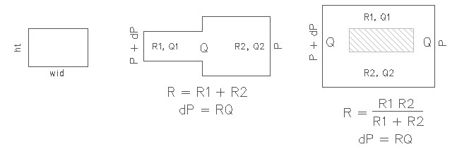
Hagen-Poiseuille law is analogous to the Ohm's law dV = RI that relates the current I through a wire of resistance R and an electrical potential drop of dV. Similar to electrical resistors connected in series, two channels with different hydraulic resistance can be modeled by summing the two hydraulic resistance together as shown in the picture above. On similar lines, two hydraulic resistors connected in parallel follows the law of additivity of inverse of their hydraulic resistances as shown in the figure.
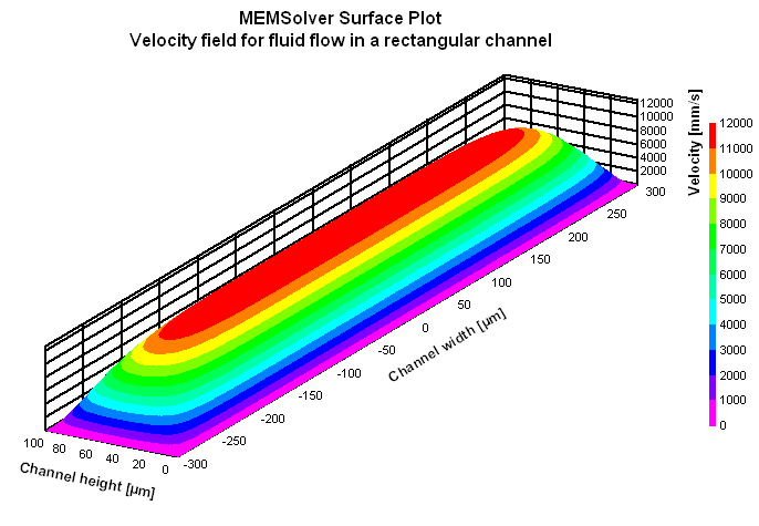
Use this design form to calculate the hydraulic resistance of a rectangular microfluidic channel with constant cross sectional area. If the channel has varying cross sectional area, the hydraulic resistance for individual channels with constant cross section can be found using this design form and then added together using the additivity law explained above. The flow rate can then be estimated using the Hagen-Poiseuille law. The average flow velocity is approximately one half of the maximum velocity which is at the center of the channel. To find the time the fluid takes to travel the full length of the channel, divide the length of the channel with the flow velocity.
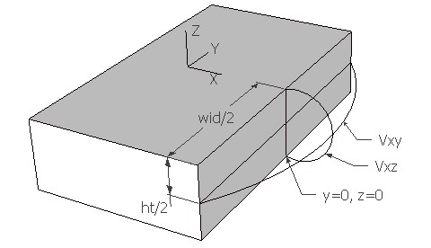
The plot shows the velocity field for the Poiseuille flow in a rectangular channel. The plot in blue color shows the velocity field along the center line parallel to the width of the channel. This plot is Vx(y,ht/2) shown as Vxy in the plot and picture above. The plot in red color shows the velocity field along the center line parallel to the height of the channel. This plot is Vx(0,z) shown as Vxz in the plot and picture above. The maximum velocity can be found out from the velocity field plot which happens at the center of the channel.