
Notes
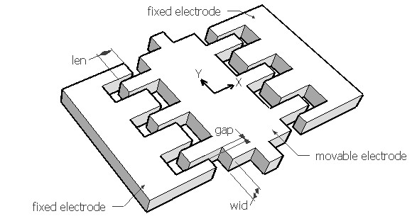
The comb drive actuator typically consists of a movable electrode
consisting of one or more finger like features forming a
interdigitated comb like pattern with a fixed electrode. The
interdigitated pattern ensures that the normal force between the
electrodes in Y direction are canceled out. When a voltage is
applied between the movable electrode and one fixed electrode,
based on which fixed electrode is activated, the movable electrode
will move laterally in X direction towards it. This movement will
continue till the tangential electrostatic force due to all the
active fingers are balanced by the elastic force of the spring
suspension. This position is the balanced displacement and the
corresponding electrostatic force is the actuation force. Actuation
force is independent of the overlapping distance. The spring
suspension is not shown in the figure, but the comb drive is
designed to move in X direction and should be prevented from moving
in Y direction. So the spring constant should be calculated for Y
axis and based on that the beam design should be done. The movable
electrode in the picture has six fingers, only three of which on
one side will be activated at one time.
Using this design form, the balanced displacement, the actuation force and the minimum spring constant to prevent Y axis movement can be estimated. Assuming the supply voltage is the critical voltage that would force the fingers to move in Y direction, the minimum spring constant required in Y axis is calculated. If the spring constant is below this value, for the given voltage, the movable electrode will become unstable and move in Y axis till it hits the fixed electrode. Keeping the spring constant in Y above this value would ensure that the comb-drive is stable.
The plot shows the relationship between the applied voltage and the lateral displacement for the given comb drive. Using the crosshair tool, the displacement for any given voltage upto 20V can be estimated.