Notes
Diaphragms or membranes as it is sometimes called, form the basic
structural element of MEMS pressure sensors. They are easy to
fabricate, offer good dynamic response and can be used over a wide
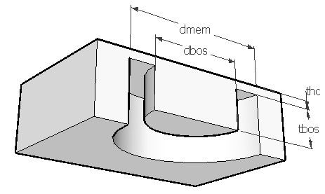
range of pressures. To improve sensitivity and linearity of a flat
diaphragm, the center portion of the membrane is often made thicker
so as to form a bossed diaphragm as shown in the figure. Such a
diaphragm would exhibit higher stresses for the same deflection or
lower deflection for the same stress levels. This makes the bossed
design more linear when compared to a flat diaphragm. Also the thin
annular area allows concentration of stress to improve the
sensitivity of the device. It is particularly useful in sensing low
pressure signals. The boss also provides over load protection. The
boss ratio 'dbos/dmem' should be greater than 0.15 and thickness
ratio 'tbos/thc' should be greater than six for the boss to be
effective.
In this model, the outer perimeter of a round bossed diaphragm is held firmly and a uniform pressure amounting to the full scale pressure is applied from top. The applied pressure will deflect the diaphragm till the elastic forces balance the pressure. When the applied pressure is small, the deflection of the membrane is linear. But at higher pressures, the strain in the neutral axis will increase to a level which cannot be neglected. This will introduce a nonlinearity term in the calculation of deflection at higher pressures.
The piezoresistor should be located at maximum stress locations near the edge. For a bossed diaphragm, the stress near the rim of the boss is same in magnitude but opposite in sign to the stress at the outer perimeter. The relative change in resistance of the piezoresistor is related to the stress, the piezoresistive coefficients and the angle of placement with respect to the edge of the membrane. Typically four piezoresistors, two placed longitudinally to the stress and two placed transversely are connected in a Wheatstone bridge. The relative change in resistance of the piezoresistors are registered as an output voltage proportional to the supply voltage connected to the bridge. The supply voltage is assumed to be 5V. The piezoresistors are assumed to be of p-type with rectangular shape.
This design interface can be used to determine the sensitivity, deflection nonlinearity and burst pressure of a round bossed diaphragm. Sensitivity is defined as the change in output voltage for a unit change in pressure at 5V supply. The output at any other supply voltage can be calculated from this. Deflection nonlinearity is defined as the difference in center deflection due to the nonlinearity term explained earlier, expressed as a percentage of the linear deflection. Burst pressure is a theoretical limit for the pressure that can be applied to the diaphragm without rupturing the diaphragm. The maximum allowable stress is assumed to be 2GPa for this calculation. This could vary depending on the features peculiar to the given membrane like etch deformities and defects.
The plot shows the span of the pressure sensor as a function of membrane thickness. Span is the output of the sensor at the full scale pressure and 5V supply to the Wheatstone bridge circuit. Using the crosshair tool, the span at any diaphragm thickness can be estimated.